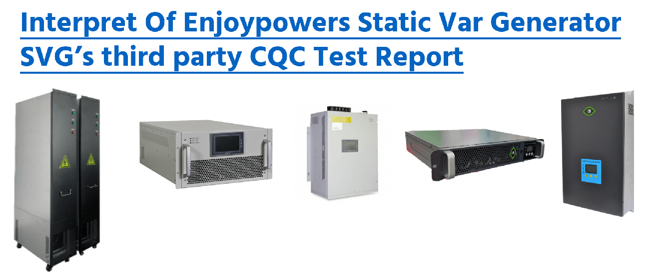
All power quality products of Enjoypowers Technology have passed the third-party test of CCIC Southern Testing Co., LTD and obtained the CQC certificate.
In order to facilitate partners to understand the performance of Enjoypowers’ power quality products, I will share the entire SVG test report with you based on the Static Var Generator SVG test report issued by CCIC-SET.
Table of Contents
About CCIC-SET
Established in 1985, CCIC Southern Testing Co., LTD is a holding company of China Inspection and Certification Group (CCIC) and a third-party inspection and testing technical institution with an independent legal personality. He has won the “National Quality Certification Qualification Unit (CMA)”, “China National Accreditation Service for Conformity Assessment (CNAS) Accredited Laboratory”, “China Quality Certification Center (CQC) Contract Laboratory”, “TUV Rheinland Authorized Third-Party Testing” Laboratory” and other more than 20 important qualifications at Chinese and foreign qualifications.

Enjoypowers’ Static Var Generator SVG test report background
Application number: V2019CQC020018-467031
Report number: C-02101-V202008674(XG1)
Product name: SVG
Model: SinE-100S44L
Testing agency: CCIC Southern Testing Co., Ltd.
Completion Date: April 3, 2020
Applicant: Enjoypowers
Test basis standard: DL/T 1216-2013 “Technical Specification for Static Var Compensation Device for Distribution Network”
Test sample description and description
Main components
Filter capacitor, filter inductor, IGBT, DC bus capacitor, fuse, controller, fan
Operation mode
After the device is powered on, it starts automatically, and the system enters the normal working state.
Control method
The device control system collects and detects the load signal, analyzes the load-side reactive current through the control algorithm, and controls the converter module composed of IGBTs through PWM to actively send out a reactive current with the same amplitude and opposite direction as the load-side reactive current. The current offset the reactive current in the grid, thereby realizing the function of compensating reactive power.
Workplace
Pollution level PD2, the working environment temperature is -25°C-45°C, the rated power working environment temperature is 45°C, the ambient temperature is greater than 45°C, and the derating is used. The working altitude is below 2000m, when the altitude is greater than 2000m, derating is used. The relative humidity of the environment is 5%-95%, without condensation.
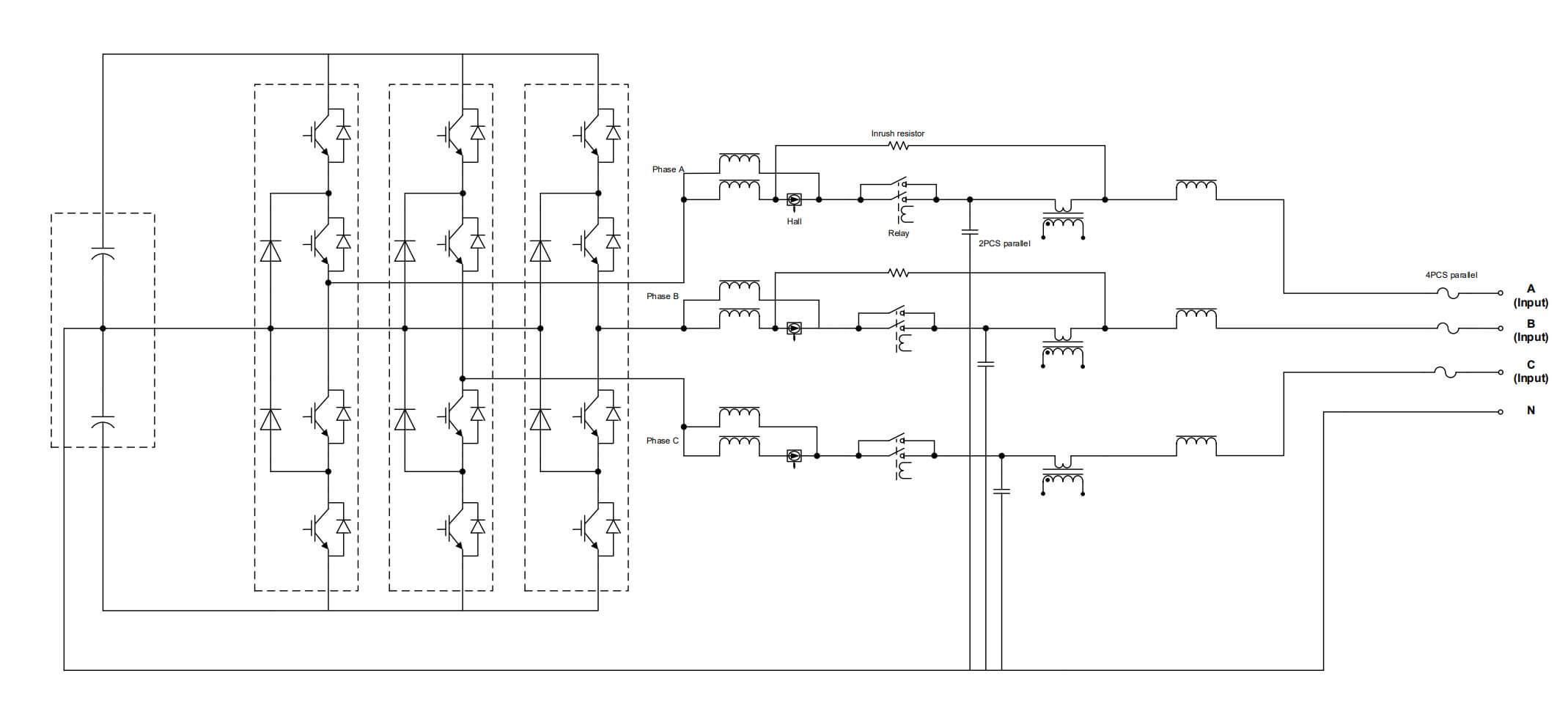
Working principle diagram
Test items and results
| No. | Test items | Test result | |
| 1 | Visual and structural inspection | qualified | |
| 2 | Protection class test | qualified | |
| 3 | Clearance and Creepage Distance Inspection | qualified | |
| 4 | Dielectric Strength Test | Insulation resistance verification | qualified |
| 5 | Power frequency withstand voltage test | qualified | |
| 6 | Lightning impulse test | not applicable | |
| 7 | AC voltage test between commutation chain terminals | not applicable | |
| 8 | Accuracy measurement test | qualified | |
| 9 | Protection test | qualified | |
| 10 | temperature rise test | qualified | |
| 11 | performance test | Continuous Operating Range Test | qualified |
| 12 | Voltage control test | not applicable | |
| 13 | Constant reactive power control test | qualified | |
| 14 | Reactive power tracking control test | qualified | |
| 15 | Power factor control test | qualified | |
| 16 | Step Response Test | qualified | |
| 17 | Loss assessment | qualified | |
| 18 | Harmonic test | qualified | |
| 19 | Output harmonic test | qualified | |
| 20 | Harmonic compensation test | qualified | |
| 21 | Continuous running test | qualified | |
| 22 | Noise test | qualified | |
| 23 | Electromagnetic Compatibility Test | Radiated electromagnetic field interference test | qualified |
| 24 | Fast transient disturbance test | qualified | |
| 25 | Burst interference test | qualified | |
| 26 | Electrostatic discharge interference test | qualified | |
| 27 | Telephone and Radio Interference Testing | qualified | |
Important test items and results
Dielectric strength test insulation resistance verification
Results of measurements and observations:
Between phase conductors: >100MΩ
Between phase conductor and shell: >100MΩ
Dielectric strength test Power frequency withstand voltage test
The applied voltage is: 2500Vac The sample has no discharge phenomenon and no damage
The applied voltage is: 3750Vac The sample has no discharge phenomenon and no damage
Accuracy measurement test
Relative error at 100% rated inductive reactive power output
| Voltage/current | Display value | Test value | Error value | |
| Voltage | A | 229 | 228.939 | 0.03% |
| B | 229 | 228.687 | 0.14% | |
| C | 229.1 | 229.889 | -0.34% | |
| Current | A | 149.7 | 149.069 | 0.42% |
| B | 146.2 | 145.995 | 0.14% | |
| C | 152.6 | 152.436 | 0.11% | |
Relative error at 100% rated capacitive reactive power output
| Voltage/current | Display value | Test value | Error value | |
| Voltage | A | 236 | 235.245 | 0.32% |
| B | 236.7 | 236.054 | 0.27% | |
| C | 236.4 | 236.459 | -0.02% | |
| Current | A | 145 | 144.899 | 0.07% |
| B | 142 | 141.972 | 0.02% | |
| C | 148.2 | 148.038 | 0.11% | |
Protection test
- The device has a power-on self-test function. When the self-test is abnormal, all operations are locked, and the alarm indicator is on.
- The device has a synchronization signal;
- Protection function
| Protection item | Test process | Difference |
| DC bus overvoltage | The overvoltage protection value of half the DC bus of the device is 390v. When the voltage of the DC bus rises to 390.25v, the device immediately reports “bus overvoltage” and stops operation, and the alarm indicator is on. | <±5% |
| DC bus Undervoltage | The overvoltage protection value of the half DC bus of the device is 300V. When the voltage of the DC bus rises to 299.8v, the device immediately reports “bus Undervoltage” and stops operation, and the alarm indicator is on. | <±5% |
| Drive board fault | Disconnect the drive cable, stop the device for protection, and the alarm indicator is on. | qualified |
| Device over-temperature protection | The NTC over-temperature protection value of the device is set to 80 ℃. When the temperature reaches 79.8 ℃, the device immediately reports an “abnormal temperature” and stops operation, and the alarm indicator is on. | <±5% |
| AC overvoltage | Set the overvoltage protection value of the device to 268v and slowly increase the input voltage. When the voltage reaches 268.9v, the device will immediately report “grid overvoltage” and stop operation, and the alarm indicator will be on. | <±5% |
| AC Undervoltage | Set the Undervoltage protection value of the device to 130v and slowly reduce the input voltage. When the voltage reaches 131.9v, the device immediately reports “grid Undervoltage” and stops operation, and the alarm indicator is on. | <±5% |
| Overcurrent | The single module overcurrent protection value is set to 160A. When the analog rapidly increases the output current to 154.6a, the device immediately reports “output overcurrent” and stops operation, and the alarm indicator is on. | <±5% |
| Abnormal cooling system | If the fan of the analog device fails, the device will immediately report “fan failure” and the alarm indicator will be on. | qualified |
Temperature rise test
Ambient temperature (℃): 25.3
Test current: main circuit 150A
Connecting conductor: Cross-sectional area 50㎡, The length shall not be less than 2m
| Measuring point | Temperature rise K | Temperature rise limit K |
| R5 soft starter resistance | 12.5 | 30 |
| L2 inductance | 35.7 | 125 |
| F1 fuse | 29.9 | 65 |
| L13 inductance | 24.2 | 125 |
| L14 inductance | 30.5 | 125 |
| M4 T1 transformer | 33.1 | 125 |
| Rly7 relay | 36.3 | 45 |
| T3 transformer | 34 | 45 |
| T6 coil | 16.7 | 125 |
| C7 capacitance | 20.4 | 45 |
| C19 filter capacitor | 16 | 45 |
| U9 main chip | 29.3 | 90 |
| U10 main chip | 30.5 | 90 |
| Enclosure | 10.2 | 20 |
| HMI | 10 | 20 |
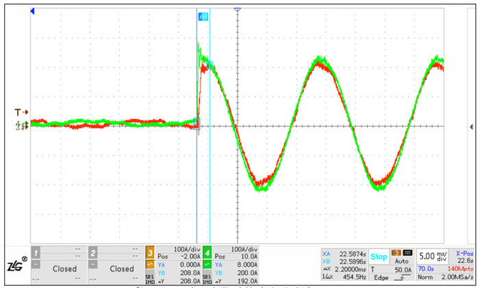
Performance test: step response test
| Step response time (ms) | |
| 0~100kVar | 2.2 |
| 100 kVar ~0 | 2.96 |
| 0~-100kVar | 4.76 |
| -100 kVar ~0 | 1.84 |
| 100 kVar ~-100kVar | 7.8 |
| -100 kVar ~100kVar | 3.88 |
Performance Test: Operational Efficiency
The measured loss values are as follows when operating under the conditions of rated voltage and rated current:
| Set value
(kVar) |
Measured active power
(kW) |
loss | |
| Allowable value | Measured value | ||
| 101.402 | 2.445 | 2.50% | 2.41% |
| -100.824 | 2.432 | 2.50% | 2.41% |
Performance test: power factor control test
Set the device to power factor control mode, and adjust the target power factor setting value so that the device output changes from the maximum inductive reactive current to the maximum capacitive reactive current. The measured power factor data are as follows:
| Power factor setting value | Phase | Load PF | Grid PF | Difference |
| 0.9 | A | 0.6 | 0.89527 | -0.52% |
| B | 0.6 | 0.88876 | -1.24% | |
| C | 0.6 | 0.87994 | -2.22% | |
| -0.9 | A | 0.6 | 0.90274 | 0.27% |
| B | 0.6 | 0.90759 | 0.84% | |
| C | 0.6 | 0.90801 | 0.89% | |
| 0.9 | A | 0.6 | 0.90752 | 0.83% |
| B | 0.3 | 0.90714 | 0.79% | |
| C | 0.95 | 0.89889 | -0.12% | |
| -0.9 | A | 0.6 | 0.91494 | 1.66% |
| B | 0.3 | 0.89524 | -0.52% | |
| C | 0.95 | 0.89795 | -0.22% |
Performance test: Output harmonic test
In the constant reactive power control mode, the rated inductive output capacity and the rated capacitive output capacity test the total harmonic current distortion rate of the output current respectively. The data are as follows:
| Set value
(kVar) |
THDi (%) | ||
| A | B | C | |
| 100 | 2.198 | 2.255 | 2.721 |
| -100 | 2.456 | 2.784 | 2.82 |
Performance test: Compensated Harmonic Test
Before and after compensation, the three-phase current size, waveform, and harmonic content of each current and the total harmonic current distortion rate of the system shall satisfy the ratio of the current root mean square value after harmonic and before harmonic ≤50%.
The main circuit input is 230V, and the harmonic source emits harmonic current less than or equal to the 13th order. The harmonic current values before and after compensation are recorded by the power analyzer. The calculated ratio of the current rms value after harmonic and before harmonic is as follows:
| A | B | C | |
| Harmonic current value before compensation (A) | 98.583 | 99.001 | 99.019 |
| Harmonic current value after compensation (A) | 18.089 | 18.291 | 17.842 |
| The ratio of post-harmonic to pre-harmonic current rms value (%) | 18.35 | 18.48 | 18.02 |
Performance test: Noise test
Rated load and ambient noise ≤40dB; 1m from the horizontal position of the noise source, the maximum measured noise of the device is ≤70dB.
| Noise(dB) | |||
| forward | back | left | right |
| 54.6 | 50.1 | 49.8 | 52.1 |
Performance test: Radiated electromagnetic field interference test
Judgment criteria
| Function | acceptance criteria |
| Protect | Normal performance within specified limits |
| Command and control | |
| Measurement | |
| HMI and alarms | |
| communication |
Test type: indoor type
Application site: module
Distance between sample and antenna: 3m
Polarity: H/V
Frequency range: 80MHz-2.7GHz
Test level: 10V/m
The device display and work should be normal.
Layout diagram for the test equipment
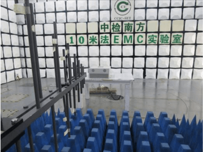
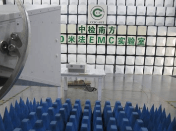
There were no dangerous or unsafe consequences during the entire test, and the EUT worked normally after the test, showing immunity to interference. meet the criteria for determination.
Performance test: Burst interference test
Judgment criteria:
| Feature | Acceptance Criteria |
| Protection | Normal performance within specified limits |
| Command and Control | Normal performance within specified limits |
| Measurement | The performance drops temporarily during the test, and recovers after the test without losing the stored data |
| HMI and visual alarms | Temporary reduction in performance or loss of function during the test, Self-recovery after the test, the stored data is not lost |
| Data communication | Bit error rate may increase without loss of transmitted data |
- Application position: line-line
Test voltage: 1KV
Test polarity: +, –
Oscillation frequency: 0.1 MHz
Repetition rate: 40 times/s
Application time: 2min
The device display and work should be normal.
- Application position: line-line
Test voltage: 1KV
Test polarity: +, –
Oscillation frequency: 1 MHz
Repeat rate: 400 times/s
Application time: 2min
The device display and work should be normal.
- Application position: line-ground
Test voltage: 2.5KV
Test polarity: +, –
Oscillation frequency: 0.1 MHz
Repetition rate: 40 times/s
Application time: 2min
The device display and work should be normal.
- Application position: line-ground
Test voltage: 2.5KV
Test polarity: +, –
Oscillation frequency: 1 MHz
Repeat rate: 400 times/s
Application time: 2min
The device display and work should be normal.
The following figure shows the test layout:
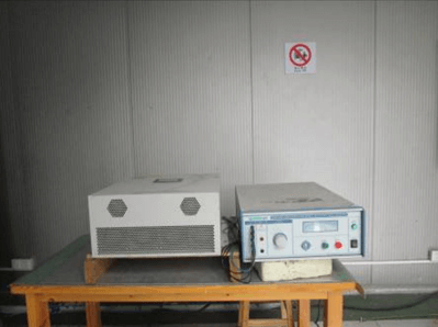
Performance test: Electrostatic discharge test
Judgment criteria:
| Feature | Acceptance Criteria |
| Protection | Normal performance within specified limits |
| Command and Control | Normal performance within specified limits |
| Measurement | The performance drops temporarily during the test, and recovers after the test without losing the stored data |
| Human-Machine Interface and Visual Alarms | Temporary reduction in performance or loss of function during the test, Self-recovery after the test, the stored data is not lost |
| Data communication | Bit error rate may increase without loss of transmitted data |
After the device is powered on, the following interference signals are applied:
Applied voltage value: 8kV
Discharge voltage polarity: positive, negative
Discharge method: air discharge
Implementation: Direct Discharge
Discharge times: 10 times
Time interval between two discharges (s): 1s
Application site: shell, gap and operation panel
After the test, the device displays and works normally.
Applied voltage value: 6kV
Discharge voltage polarity: positive, negative
Discharge method: contact discharge
Implementation: Direct Discharge and Indirect Discharge
Discharge times: 10 times
Time interval between two discharges (s): 1s
Application part: metal shell, coupling plate
After the test, the device displays and works normally.
The following figure shows the layout of the test equipment:
There were no dangerous or unsafe consequences throughout the test, and the EUT worked normally after the test, showing immunity to interference. meet the criteria for determination.
Conclusion
Enjoypowers focuses on the R&D and production of power quality products and provides OEM services for more than 480 partners in the world. All power quality products, including active harmonic filters and static var generators, have passed the strict testing of CQC, and have obtained CE, RoHs, and other certifications.
Selecting power quality products according to your specific requirements: Enjoypowers team is happy to assist you to select and calculate the appropriate AHF or module size and implement a power quality solution that perfectly meets your requirements.
For this, please send us your application data and contact me: [email protected], Or connect with me on LinkedIn.