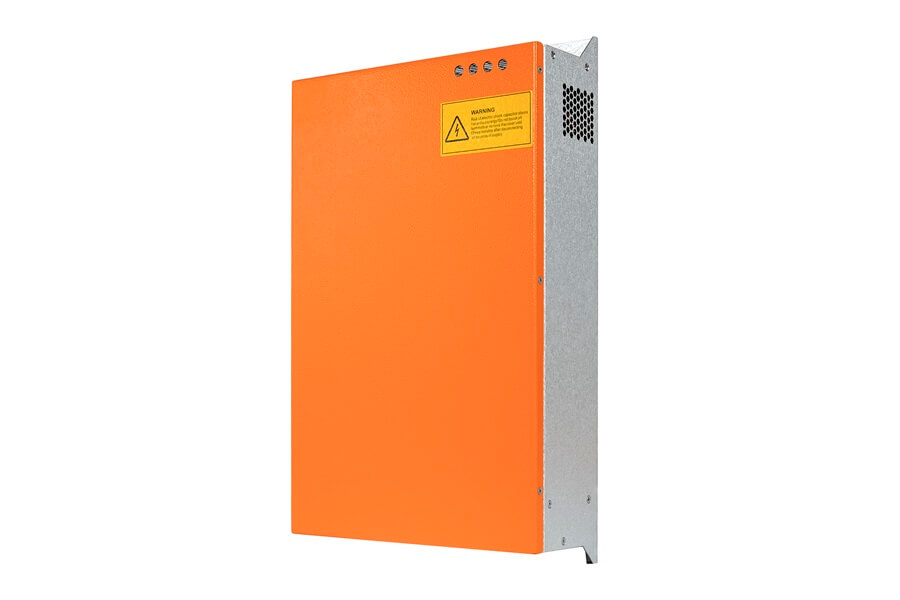
In the realm of power quality solutions, Static Var Generators (SVGs) have emerged as indispensable tools for enhancing grid stability and mitigating voltage fluctuations. As the demand for reliable and efficient electrical systems continues to soar, understanding the detailed installation process of SVG modules, including Current Transformers (CTs), becomes crucial for businesses seeking to optimize their power infrastructure. In this comprehensive guide, we’ll walk you through the step-by-step procedure of installing SVG modules with a focus on CT integration, empowering you to bolster grid stability and elevate power quality standards.
Table of Contents
1. Pre-Installation Preparation
Before commencing the installation of SVG modules, thorough pre-installation preparation is essential to ensure seamless integration and optimal performance. This phase involves:
- Conducting a comprehensive site assessment to identify optimal placement locations for SVG modules and CTs.
- Reviewing electrical schematics and grid configurations to determine CT placement and wiring requirements.
- Procuring necessary equipment, including mounting hardware, cables, CTs, and auxiliary components, to facilitate the installation process.
2. Mounting and Positioning
Once the pre-installation preparations are complete, the next step involves mounting and positioning the SVG modules and CTs according to the site assessment findings. Key considerations during this phase include:
- Ensuring adequate ventilation and clearance around the SVG modules and CTs to facilitate heat dissipation and prevent overheating.
- Securing the modules and CTs to sturdy mounting structures using appropriate hardware to withstand environmental factors and mechanical stresses.
- Positioning the CTs in strategic locations to accurately measure current flow and enable precise control of reactive power compensation.

3. Electrical Connection and CT Integration
With the SVG modules and CTs securely mounted, the focus shifts to establishing electrical connections and integrating the CTs into the existing power infrastructure. This phase entails:
- Terminating incoming and outgoing power cables, as well as CT secondary wiring, according to manufacturer specifications and industry standards.
- Conducting insulation resistance tests and continuity checks on CT circuits to verify the integrity of electrical connections and ensure safety compliance.
- Configuring communication interfaces and control settings to enable seamless integration of CT data with supervisory control and data acquisition (SCADA) systems for remote monitoring and control.
4. Commissioning and Testing
Once the SVG modules and CTs are electrically connected and integrated, the commissioning and testing phase begins to validate system functionality and performance. This phase involves:
- Energizing the SVG modules and CTs and conducting initial startup procedures to verify proper operation and functionality.
- Performing current measurements using CTs at various points within the power distribution network to assess reactive power compensation and ensure accurate power factor correction.
- Conducting transient and steady-state tests to evaluate dynamic response and stability under varying load conditions, with particular emphasis on CT accuracy and responsiveness.
5. Operational Optimization
After successful commissioning and testing, the final phase involves operational optimization to fine-tune the performance of the SVG modules and CTs and maximize grid stability. This phase includes:
- Analyzing real-time data and performance metrics from CT measurements to identify opportunities for efficiency improvements and system optimization.
- Implementing control adjustments and parameter tuning based on CT feedback to optimize reactive power compensation and voltage regulation in response to changing grid conditions.
- Providing comprehensive training to operational staff on CT installation, calibration, and troubleshooting protocols to ensure ongoing reliability and performance.
Conclusion
In conclusion, the installation process of SVG modules with CT integration represents a critical step towards enhancing grid stability and optimizing power quality in electrical systems. By following the step-by-step guide outlined in this article, businesses can navigate the complexities of SVG module and CT installation with confidence, unlocking the full potential of these transformative power quality solutions.
Related Reading
5 Key Steps to Designing an Exceptional SVG Cabinet for Enhanced Power Quality
SVG Tackle Power Factor Drop in Commercial PV Solar projects
How to Achieve High-Voltage Side power factor correction
How to Size Your SVG Modules for Optimal Power Factor Correction
Analysis of Three different power factor correction solutions
Optimizing Energy Efficiency: Power Factor Correction Explained
